عن ماذا تبحث?
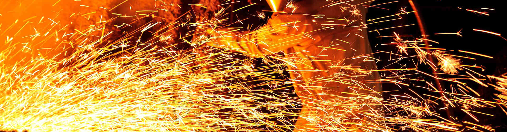
An automotive hose heat protection sleeve creates a flexible thermal barrier around the exposed section. The correct sleeve can help reduce external radiant heat while allowing the hose or tube to retain the flexibility, routing and service access required by the vehicle assembly.
Selection should not be based only on a sleeve temperature rating. The line type, internal fluid temperature, external heat source, clearance, fitting dimensions, bend radius, vehicle movement, installation sequence and required validation all influence the final design.
BSTFLEX manufactures aluminized heat protective sleeves for automotive hoses, fluid lines, wire harnesses and cable assemblies in tubular, sewn, wrap-around, self-closing and custom configurations.
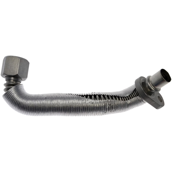
Vehicle fluid lines carry fuel, brake fluid, lubricating oil, coolant, transmission fluid, hydraulic fluid, refrigerant and emissions-related media. These lines may pass close to hot surfaces because of restricted engine-compartment space, system packaging, sensor position or underbody routing.
Excessive external heat can affect more than the fluid inside the line. The complete assembly may include:
Each component may have a different thermal limit. A hose assembly should therefore be evaluated as a complete system rather than selecting protection only from the temperature capability of the sleeve material.
A thermal sleeve does not automatically cool the fluid inside a hose. Its primary function is normally to reduce heat entering the line from an external source.
This distinction is important because some fluid lines already carry hot media. An engine-oil return line, transmission-fluid line or coolant hose may have a significant internal temperature before external radiant heat is considered.
Adding insulation around a line can reduce external heat exposure, but it may also reduce the line's ability to release internally generated heat. The thermal objective must therefore be defined before the line is covered.
The engineer should determine whether the requirement is to:
These are different thermal problems and may require different sleeve constructions.
Before selecting a hose heat shield sleeve, identify how heat reaches the line.
Radiant heat travels from a hot surface toward the hose without direct contact. Exhaust manifolds, turbine housings, downpipes, catalytic converters and exhaust-aftertreatment systems are common radiant heat sources.
An aluminized reflective outer surface is particularly useful in this condition because it helps reduce radiant energy absorbed by the sleeve and hose assembly.
A hose may operate inside a generally hot engine compartment even when it is not directly facing one exhaust component. In this condition, reflective protection may need to be combined with additional insulation.
If a hose or sleeve touches a hot surface, heat transfers by conduction. A thin reflective sleeve should not be treated as a substitute for correcting insufficient clearance or improper routing.
Where continuous contact cannot be avoided, a thicker multi-layer construction, a source-side shield or a redesigned hose route may be required.
Air heated by the exhaust system can move through the engine compartment and expose hose sections that are not directly facing the heat source. The protected length should therefore be based on the complete heat-affected zone rather than one visible hot spot.
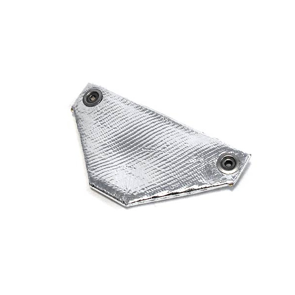
Fuel lines are commonly routed through engine compartments and underbody areas where they may pass close to exhaust manifolds, turbocharger systems, catalytic converters and hot engine surfaces.
A reflective sleeve can be used to reduce external radiant heat reaching the fuel hose or tube. Selection should consider:
For a product designed specifically around fuel and brake line applications, see the BSTFLEX Fuel and Brake Line Aluminum Heat Shield Sleeve.
Brake tubes and flexible brake hoses may pass near exhaust piping, wheel-end heat sources or other high-temperature vehicle components.
Protection should be designed without interfering with:
A sleeve must remain securely positioned while allowing the hose to move through its intended range. It should not create a new rubbing point against brackets, wheel components or suspension parts.
For rigid brake tubing, a compact aluminized sleeve may be suitable where the main problem is radiant heat from a nearby exhaust component. Flexible brake hoses may require additional attention to bend radius, movement and retention.
Oil feed and return lines can be located close to turbocharger turbine housings, exhaust manifolds and downpipes. These lines may already carry hot oil, so the thermal specification should separate internal fluid temperature from external heat exposure.
Important design questions include:
A reflective sleeve may reduce radiant heat from the turbocharger, but the complete line temperature should still be evaluated under the intended operating cycle.
Transmission-fluid and transmission-cooler lines may be routed near exhaust systems, catalytic converters or hot transmission components.
A transmission line heat shield can be designed around a flexible hose, rigid tube or combined hose-and-tube assembly. The specification should identify whether the line carries hot fluid toward a cooler, returns cooled fluid or operates in another part of the transmission circuit.
For transmission-line projects, provide:
The sleeve should not prevent inspection of fittings or create excessive stiffness at flexible transition points.
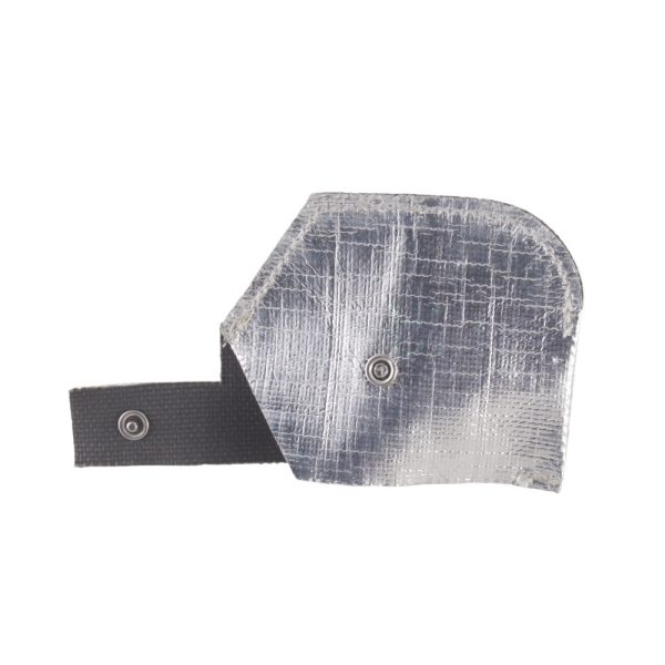
Coolant and heater hoses may pass near exhaust manifolds, turbochargers, EGR components and other concentrated heat sources.
A coolant hose heat sleeve is generally selected to reduce external radiant heat reaching the hose wall. It does not change the requirement for correct coolant-system design or appropriate hose material.
Particular attention should be given to:
A straight tubular sleeve may not follow a complex molded coolant hose without wrinkling or shifting. Sewn, segmented or wrap-around constructions can provide better coverage around irregular geometry.
Automotive air-conditioning systems contain multiple refrigerant lines that can have different thermal functions. A protection sleeve should therefore be applied only after the purpose and operating condition of the specific line are understood.
Relevant project information includes:
A low-profile reflective sleeve may be useful where an A/C hose passes through a restricted engine-compartment area near a radiant heat source.
Hydraulic and power-steering hoses can be exposed to radiant heat, abrasion, vibration and fluid contamination at the same time.
Thermal protection must not compromise hose flexibility, pressure-service inspection or fitting access. The sleeve should also remain stable when the hose moves during vehicle or equipment operation.
For hydraulic hose applications, evaluate:
Where both radiant heat and abrasion are significant, the protective construction may require separate thermal and mechanical layers rather than relying on one thin reflective surface.
DEF, urea and SCR system lines can be routed through exhaust-aftertreatment areas where high-temperature components are concentrated.
These assemblies may include:
The heat shield may therefore need to protect a combined hose-and-wire assembly rather than a simple fluid tube.
For irregular assemblies with connectors, branches or valves, a component-specific shaped shield may provide more controlled coverage than a standard tubular sleeve.
An aluminized fiberglass sleeve combines a reflective aluminum outer surface with a flexible fiberglass textile structure.
This construction is commonly evaluated where radiant heat from an exhaust component is the dominant problem and continuous direct contact is not expected.
Possible constructions include:
The reflective surface should normally face the external heat source. The fiberglass structure remains between the reflective layer and the protected hose or line.
A single reflective layer may not provide sufficient thermal separation when the heat source is very close, exposure is prolonged or the allowed line temperature is low.
A multi-layer design may combine:
Additional layers increase thickness and can reduce flexibility. Available space, hose bend radius and fitting clearance must therefore be considered before increasing the wall construction.
Some applications require changes beyond installing a sleeve.
Consider a source-side heat shield, routing change or combined protection system when:
A source-side shield can reduce the thermal load affecting multiple nearby components. In restricted areas, the most effective solution may combine source shielding with local hose protection.
A slide-on sleeve is installed by passing the hose or tube through a continuous tubular construction.
It is generally most suitable when:
A tubular sleeve can provide a compact finished profile, but fitting size must be checked before specifying the sleeve diameter.
A wrap-around sleeve opens along its length and can be installed around an existing hose or fluid line.
This design is useful when:
BSTFLEX offers an aluminized wrap-around sleeve with hook-and-loop closure for hoses, cables and assemblies that require removable radiant heat protection.
A self-closing sleeve opens to accept the hose or line and then closes through an overlapping structure or integrated edge system.
This design can reduce installation steps while avoiding the need to pass large fittings through a tube.
See the BSTFLEX Self-Closing Aluminum Foil Fiberglass Sleeve for this type of installation structure.
Snap fasteners provide defined closure points along an openable sleeve. They can be useful where the protective component must be installed repeatedly in a controlled position.
Important design inputs include:
For this construction, see the BSTFLEX Heat Reflective Sleeve with Snap Closure.
Correct sizing begins with the actual outside dimensions of the completed hose assembly.
Do not select the sleeve only from the nominal hose inside diameter. A hose described by its fluid-bore size can have a substantially larger outside diameter after reinforcement and outer covering are included.
Measure and record:
For an openable sleeve, also define the required overlap and closure position.
The largest part of the assembly often determines whether a tubular sleeve can be installed.
For example, the hose body may fit a compact sleeve while the crimp ferrule or connector is significantly larger. There are several possible solutions:
The chosen method should maintain practical installation without leaving an uncontrolled loose sleeve around the normal hose diameter.
Heat sleeves may be specified by inside diameter, finished diameter, flat width or another construction-specific dimension.
These measurements are not interchangeable without understanding the product structure.
For a custom RFQ, identify whether the stated dimension refers to:
This prevents confusion when comparing tubular and wrap-around products.
Automotive hoses rarely remain perfectly straight. They may curve around engine components, move with the powertrain or flex during steering and suspension movement.
A sleeve should follow the intended bend without:
Thicker multi-layer sleeves may require a larger bending radius than a thin reflective sleeve.
The sleeve should cover the full heat-affected section rather than only the point directly opposite the heat source.
When defining length, consider:
A sleeve that is too short can leave the hose transition or fitting exposed. A sleeve that is unnecessarily long may interfere with clamps, identification labels or service access.
Metal fittings can conduct heat toward the hose assembly. In some applications, protecting only the flexible hose section may leave the fitting within the same high-temperature zone.
However, covering a fitting can also make inspection and servicing more difficult.
The specification should clearly state whether the sleeve must:
This decision should be based on the thermal requirement and maintenance process.
A reflective sleeve works primarily by reducing radiant heat absorbed by the protected assembly. The space between the heat source and reflective surface is part of the thermal design.
If engine movement, vibration or hose sag causes the sleeve to rest against the exhaust component, the heat-transfer condition changes from predominantly radiant to conductive.
Check clearance:
The aluminized surface should normally remain exposed toward the external radiant heat source.
Avoid installation that:
Where orientation is important, use a suitable retention system or a shaped part that can only be installed in the correct position.
A heat sleeve must remain over the intended section during vibration, vehicle movement and maintenance.
Possible retention methods include:
The retention system should not crush the hose, restrict fluid flow, damage the outer cover or create a stress concentration near the fitting.
A hose sleeve may contact brackets, frame members, adjacent lines or other engine-compartment components.
Evaluate:
Where severe abrasion is expected, the thermal sleeve may need to be combined with a separate abrasion-protection layer.
The complete sleeve includes more than the visible aluminum and fiberglass layers. Adhesive, sewing thread, closure materials, edge binding and labels may all be exposed to automotive fluids.
For an OEM project, identify possible contact with:
Fluid resistance should be confirmed for the complete proposed construction rather than inferred from one raw material.
| Line Type | Typical External Heat Concern | Recommended Starting Construction | Important RFQ Detail |
|---|---|---|---|
| Fuel hose or fuel tube | Exhaust or engine radiant heat | Aluminized fiberglass sleeve | Line OD, fittings and required protected length |
| Brake line or brake hose | Exhaust, wheel-end or underbody heat | Compact reflective sleeve | Movement, inspection and fitting access |
| Turbo oil feed or return line | Turbine housing and downpipe heat | Reflective or multi-layer sleeve | Internal fluid temperature and oil exposure |
| Transmission-fluid line | Exhaust and transmission heat | Reflective tubular or wrap-around sleeve | Flow direction, fittings and cooler-line routing |
| Coolant or heater hose | Manifold, turbocharger or EGR radiant heat | Large-diameter aluminized sleeve | Molded geometry and bend radius |
| A/C or refrigerant line | Engine-compartment radiant heat | Low-profile reflective sleeve | Line function, service ports and condensation conditions |
| Hydraulic or power-steering hose | Radiant heat combined with vibration and abrasion | Reflective sleeve with suitable mechanical protection | Pressure movement, ferrule size and abrasion points |
| DEF or SCR assembly | Exhaust-aftertreatment heat | Wrap-around or custom-shaped shield | Combined hose, heater wire and connector geometry |
The proposed sleeve should be evaluated in a representative assembly rather than relying only on the material temperature rating.
Useful validation inputs include:
Mechanical validation may also include vibration, flexing, abrasion, closure retention, fluid exposure and repeated installation where relevant.
If a customer drawing or specification identifies a particular test method, the exact proposed sleeve construction should be evaluated under that requirement. Results from another material or sleeve design should not automatically be applied to the new part.
An OEM hose shield must be manufacturable and installable consistently in production.
Depending on the design, controlled characteristics may include:
Installation fixtures, cutting templates or inspection gauges may be required when the sleeve includes component-specific features.
A conventional cylindrical sleeve may not fit around manifolds, branch connections, valves, sensors, large connectors or multiple lines grouped together.
For these applications, a shaped textile heat shield can be cut and sewn around the actual assembly geometry.
BSTFLEX manufactures Custom-Shaped Aluminized Fiberglass Automotive Heat Shields for hoses, valves, connectors, sensors, wire harnesses and fluid-line assemblies that cannot be adequately protected by a straight sleeve.
| RFQ Information | Why It Is Required |
|---|---|
| Line type and fluid | Defines the application and environmental conditions |
| Hose or tube outside diameter | Defines the basic sleeve size |
| Fitting and ferrule dimensions | Determines whether slide-on installation is possible |
| Protected length | Defines the finished part length |
| Heat-source type | Identifies the external thermal condition |
| Heat-source temperature | Indicates thermal severity |
| Internal fluid temperature | Separates internal and external heat loads |
| Minimum clearance | Supports radiant heat evaluation |
| Maximum allowed hose or fluid temperature | Defines the required thermal result |
| Installation sequence | Determines tubular, wrap-around or self-closing design |
| Bend radius and movement | Defines flexibility requirements |
| Fluid and chemical exposure | Supports complete material selection |
| Abrasion conditions | Defines mechanical protection requirements |
| Required tests and documentation | Defines validation scope |
| Prototype and annual quantity | Supports tooling, production and packaging planning |
BSTFLEX manufactures thermal protection components for automotive hoses, fluid lines, wire harnesses and cable assemblies.
Available options include:
For the complete product range, visit the BSTFLEX Aluminized Heat Protective Sleeve category.
For automotive wiring rather than fluid-line protection, see Automotive Wire Harness Heat Protection Sleeves: Materials, Designs and Applications.
For a custom hose or fluid-line project, send BSTFLEX the line drawing, outside diameter, fitting dimensions, protected length, heat-source temperature, clearance, internal fluid temperature, installation method, test requirements and expected annual quantity.
It is a flexible thermal barrier installed around a hose or fluid line to reduce heat exposure from nearby exhaust, turbocharger, engine or underbody components.
Applications can include fuel, brake, oil, transmission, coolant, heater, air-conditioning, hydraulic, power-steering and emissions-system lines. The construction must be selected for the specific hose, fluid and thermal environment.
A sleeve can reduce external heat entering the line, but it does not actively cool the fluid. The final fluid temperature also depends on the system design, internal heat load, flow rate and ability of the line to release heat.
The sleeve should fit securely without excessive compression. A sleeve that is too tight can restrict flexibility and complicate installation, while an oversized sleeve may shift away from the protected zone.
No. Select the sleeve from the actual outside diameter of the completed hose or tube. Also measure crimp ferrules, fittings, connectors and locally reinforced sections.
A tubular sleeve can be installed over fittings only when its construction and diameter allow sufficient expansion. Otherwise, use a wrap-around, hook-and-loop, snap-closure or self-closing design.
An aluminized sleeve is primarily intended for radiant heat protection. Continuous direct contact introduces conductive heat and may require improved routing, additional insulation or a source-side shield.
The reflective aluminized surface should normally face the external radiant heat source. The textile or insulation side remains toward the protected hose.
The same material family may be considered, but diameter, fitting geometry, fluid exposure, movement, abrasion, internal temperature and validation requirements can differ. Each application should be specified separately.
Yes. Inside diameter, flat width, cut length, material layers, hook-and-loop closure, snap fasteners, self-closing edges, cutouts, notches, end finishing and packaging can be customized.
Provide the hose or tube outside diameter, fitting dimensions, protected length, fluid type, internal fluid temperature, external heat-source temperature, minimum clearance, required installation method, mechanical conditions, validation standard and estimated quantity.

No.10, Chuangxin North Road, Nanshan Park, Ningguo Economic and Technological Development Zone, Ningguo City, Anhui Province, China
هاتف/Whatsapp : 0086-15856303740
البريد الإلكتروني : sales@bstbraidedsleeve.com
Skype : vanesa-cheng