عن ماذا تبحث?
Generator enclosure insulation should protect the specified panels, support the required noise control and leave the designed cooling-air path unobstructed. The best material is not necessarily the thickest liner or the one with the highest fiber temperature rating. It is the construction that performs the required job in its assigned location.
A generator canopy can need a reflective barrier beside the exhaust, an acoustic liner on a service door and no additional material at a restricted cooling inlet. Treating these areas as one insulation requirement makes selection unnecessarily difficult.
BSTFLEX supplies heat barrier sheets and thermal insulation mats for material evaluation and custom conversion. This guide is for manufacturers of engineered generator-set enclosures, not for constructing a box around a portable generator. Material selection does not replace the generator manufacturer's ventilation, exhaust-routing and installation requirements.
Mark the engine, alternator, exhaust components, radiator, electrical compartment and air openings on the enclosure drawing. Assign each proposed lining area a function. The map becomes the basis for selecting materials and identifying which areas need separate approval.
| Enclosure area | Primary requirement | What to specify |
|---|---|---|
| Panel facing a manifold, turbocharger or exhaust pipe | Limit heat reaching the panel or equipment behind it. | Exposed area, source position, minimum clearance and protected-side temperature target. |
| Sidewall or service door away from the hottest components | Provide acoustic treatment where the noise assessment calls for it. | Frequency-dependent performance, installed thickness, facing and panel construction. |
| Partition beside controls or wiring | Reduce an identified external heat input. | Component temperature limits, cable openings and required cooling access. |
| Roof or removable access cover | Maintain coverage during operation and servicing. | Overhead retention, supported spans, edge condition and removal sequence. |
| Cooling inlet, discharge opening or ventilation passage | Maintain the engineered airflow and any specified acoustic attenuation. | Approved passage dimensions and airflow resistance. Do not add lining without reviewing the cooling design. |
This approach also prevents a common purchasing mistake: using one high-temperature grade across every panel while leaving the actual hot spot or airflow restriction unresolved.
A generator heat shield on an enclosure wall protects a receiving surface. Insulation fitted around the exhaust acts at the hot component. The two arrangements need different construction and attachment specifications.
For panel shielding, show the radiant path and orient the reflective face toward the source. Define the separation from the finished shield, including any permitted component movement. A material that protects the center of a panel may still leave an exposed path around an edge or opening.
For direct exhaust treatment, review the exhaust heat shield insulation range separately. Do not wrap a manifold or silencer with a canopy liner simply because its fiber is described as heat resistant.
The adhesive-backed aluminum heat shield mat combines an aluminum-facing layer, fiberglass and mounting adhesive. It is a candidate for bonded protection on suitable enclosure surfaces.
Identify the actual paint or coating and the expected temperature at the adhesive interface. Confirm contour fit, installed thickness and edge retention. Do not treat a substrate temperature rating as approval of the complete bonded assembly.
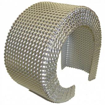
The aluminum acoustic heat shield combines a stitch-bonded E-glass needle mat with a stamped or perforated aluminum foil face. Sheets and custom die-cut requirements can be reviewed for the selected construction.
Consider this material when a panel needs both thermal and acoustic evaluation. Specify the facing and installed thickness, then request performance information for that complete composite. The product name does not establish a noise-reduction value for a finished generator enclosure.
The aluminum silica thermal barrier mat provides a woven-silica substrate with a reflective face. It can be reviewed where the hot-zone specification calls for silica.
Define the backing and retention method separately. Confirm the facing, lamination and attachment limits as well as the substrate. Selecting silica does not eliminate the need for clearance or make a flexible liner self-supporting.
Cooling air must carry heat out of the enclosure. A reflective liner can protect a surface, but it does not remove the generator's heat load. Added lining or acoustic baffles must remain within the equipment manufacturer's allowable airflow resistance.
Review the finished inlet and outlet passages, including liner thickness, retaining screens and local obstructions. Keep hot discharge air from unintentionally returning to the cooling inlet. Do not reduce ventilation openings simply to improve an external noise reading.
Show these interfaces on the liner drawing. A correctly cut insulation panel can still be unsuitable if it projects into a required air passage.
Sound absorption inside the canopy, sound transmission through its walls and vibration of the panels are different problems. The material and enclosure construction must address the relevant noise path.
A continuous foil face changes how sound interacts with the underlying fibrous layer. Perforated facing is an option to evaluate, but its performance depends on the complete construction and mounting. Do not apply acoustic data for uncovered fiber to a finished foil-faced liner.
The existing aluminum acoustic heat shield selection guide explains facing and thickness in more detail. For a generator project, the additional decision is where that construction belongs within the canopy.
A removable door liner should stop at its intended boundary rather than bridge a hinge or removable joint. Mark latches, seals, access fasteners and identification plates as keep-clear features. Confirm that the door opens, closes and can be removed with the lining installed.
For roof sections, specify retention against downward movement. An adhesive that appears satisfactory on a small vertical sample does not, by itself, approve an overhead panel. Review the actual laminate, supported area and attachment under the required thermal and vibration exposure.
Where mechanical retention is used, define support and load distribution without compressing the mat beyond its approved condition. Keep fasteners and supports independent of wiring, hoses and components not intended to carry the liner.
Use separate part references for different panels. This makes replacement and assembly checking more reliable than supplying one unmarked sheet for trimming throughout the canopy.
Identify expected oil mist, humidity, cleaning agents and possible splash. The exposed facing and cut edges should be reviewed together. A foil surface does not prove that the complete laminate is liquid-tight, washable or suitable for fuel contact.
Where the design requires edge containment or a protective facing, include those features in the sample rather than adding them after testing. Evaluate how the material is retained near airflow passages and specify acceptable surface and edge condition after service exposure.
Request the fire and smoke documentation required by the equipment specification for the actual construction, including adhesive or binder where relevant. A high fiber temperature rating is not a fire classification for the finished liner. Required evidence and its availability should be confirmed during quotation.
Prepare one validation plan for the completed enclosure. State the generator model, duty, load, ambient conditions and test duration. Use the intended door, cover and ventilation configuration; an open-door trial does not represent normal closed-canopy operation.
Thermal acceptance: identify the surfaces and components to be protected, their permitted temperatures and the measurement locations. Include relevant running and post-shutdown conditions. A cooler outer wall is not proof that every component inside the enclosure is cooler.
Cooling acceptance: verify the applicable equipment limits with the final lining and air passages installed. Record the temperatures and airflow or pressure measurements required by the generator supplier's test procedure.
Acoustic acceptance: specify operating load, measurement positions, distance and the required noise metric. Compare like-for-like conditions. A material absorption result cannot be converted directly into a guaranteed reduction in external generator noise.
After the agreed durability exposure, inspect facing condition, attachment, cutouts and service access. Record the approved material and panel revisions together. A later change to thickness, facing or coverage should be reviewed for its effect on the tested assembly.
Once the material and layout are approved, convert the coverage map into controlled parts. Identify left and right doors, roof sections, partitions and local heat-shield patches. Show the heat-facing side, critical openings and installation orientation.
BSTFLEX custom die-cut heat barrier parts provide a route for discussing finished outlines instead of repeated on-site trimming. Cutting feasibility and tolerances are confirmed for each material and drawing.
For a proposed liner kit, specify the number of each part per enclosure, labels and packing order. The custom cutting and packaging service can review counted packing and identification requirements. This is a material-and-conversion inquiry, not a claim that BSTFLEX supplies or certifies the complete generator canopy.
| RFQ field | Information to provide |
|---|---|
| Equipment and panel layout | Generator model, operating duty, enclosure drawing, panel references and installation photographs. |
| Thermal requirement | Heat-source positions, available clearance, maximum installed thickness and temperature targets at named protected locations. |
| Acoustic and cooling interfaces | Noise target and test conditions, keep-clear air passages and relevant manufacturer cooling limits. |
| Material and attachment | Facing preference, substrate, mounting-surface finish, adhesive or mechanical retention and edge requirements. |
| Approval and documentation | Sample tests, environmental exposure, required fire or smoke evidence and dimensional inspection criteria. |
| Supply format and volume | Sheets or finished parts, prototype quantity, parts per enclosure, batch volume, labels and packaging. |
Include the problem the material must solve. For example: We need a local radiant barrier for the exhaust-facing partition and a separate acoustic liner for the service doors. The attached drawing identifies the cooling passages that must remain unchanged. Please quote candidate materials and cut panels for prototype approval.
This example distinguishes the two material functions without prescribing a complete enclosure design. Send your generator canopy drawings and insulation requirements to BSTFLEX for material review and quotation.
There is no single best liner for every panel. Select a reflective barrier for an identified radiant heat path, an acoustic construction for the relevant noise treatment, and an attachment system suitable for the actual surface and exposure. Approve them within the finished enclosure.
It can change passage dimensions, local clearance and heat transfer. Added thickness should be reviewed against the cooling design and tested in the intended configuration rather than treated as an automatic improvement.
Do not assume so. A panel liner and direct exhaust insulation have different exposure and mounting requirements. Specify the exhaust treatment separately and confirm compatibility with the generator's exhaust system.
The products covered here are thermal barrier materials, acoustic composites and custom-cut parts for enclosure manufacturers. The enclosure builder remains responsible for the housing, cooling system, exhaust arrangement and approval of the complete generator assembly.

No.10, Chuangxin North Road, Nanshan Park, Ningguo Economic and Technological Development Zone, Ningguo City, Anhui Province, China
هاتف/Whatsapp : 0086-15856303740
البريد الإلكتروني : sales@bstbraidedsleeve.com
Skype : vanesa-cheng