عن ماذا تبحث?
An underbody heat shield is easy to underestimate because it often looks like a simple sheet of formed metal. In practice, the panel has to protect the vehicle floor from exhaust heat while surviving vibration, airflow, water, dirt, road contamination and repeated heating and cooling.
The correct underbody aluminum heat shield is therefore more than a reflective sheet cut to the approximate size of the hot area. Panel coverage, air gap, embossing, mounting locations, edge design and the movement of the exhaust system all influence the finished result.
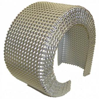
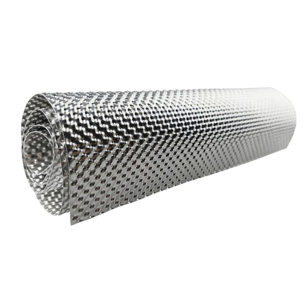
BSTFLEX supplies embossed aluminum heat shield sheet for floor pans, exhaust tunnels, transmission tunnels, bulkheads and other automotive radiant-heat barriers. The material can be cut, folded and formed to suit custom OEM thermal protection projects.
Underbody heat shielding is normally installed where an exhaust component passes close to the vehicle body or another temperature-sensitive system.
Typical locations include:
The shield does not need to follow the entire exhaust system. Its purpose is to interrupt the relevant heat path in the locations where surrounding components need protection.
The terms are often used together, but the geometry can be different.
A floor pan heat shield may be a relatively broad panel positioned beneath a section of the passenger compartment floor.
An exhaust tunnel heat shield follows the longitudinal area through which the exhaust system passes and may require a narrower, more deeply formed profile.
A transmission tunnel heat shield can cover a similar vehicle zone but must also account for gearbox dimensions, driveline movement, brackets and service access.
Do not assume that one rectangular aluminum sheet can be transferred between these installations without checking the finished geometry.
Underbody shielding often covers a larger surface area than a compact manifold or turbo shield. This makes component mass increasingly important.
Aluminum offers a useful combination of:
For a broad floor or tunnel panel, these characteristics allow engineers to create a relatively lightweight radiant barrier without using unnecessarily heavy sheet.
The correct aluminum alloy and temper still need to be selected for the forming process and mechanical requirements. For alloy selection, see Aluminum Heat Shield Material: 1050 vs 1100 vs 3003 vs 5052.
A large flat sheet can flex, vibrate or distort relatively easily. One way to increase stiffness is to use thicker metal, but this also increases weight.
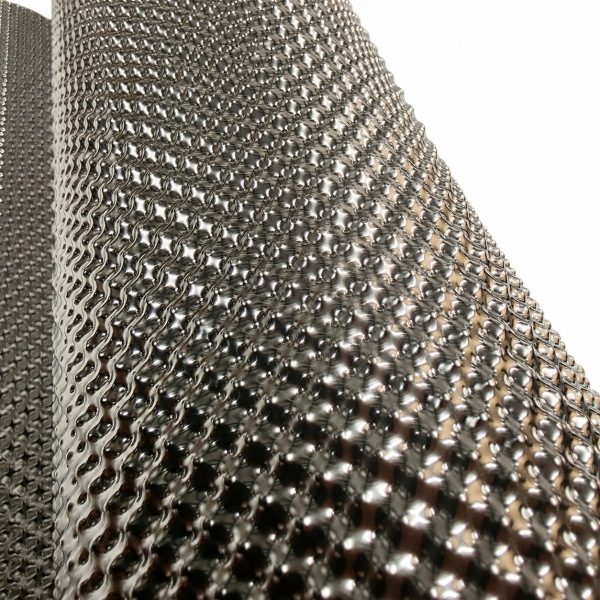
Embossing introduces three-dimensional geometry into the aluminum surface. The patterned structure can improve the rigidity of the panel and help it maintain its shape after cutting and forming.
This is particularly useful for:
The embossing pattern should be considered together with base-metal thickness, finished panel geometry and the subsequent forming process.
For a detailed explanation of the structural role of embossing, see Embossed Heat Shield Material: Why Embossed Metal Is Used for Automotive Heat Shields.
A rigid aluminum heat shield is normally most effective as part of a separated barrier system rather than as an undefined metal layer pressed directly against the hot exhaust component.
A controlled space between the exhaust and the shield helps limit direct conductive heat transfer. The aluminum panel can then function primarily as a barrier against radiant heat reaching the floor or other protected component.
The drawing should identify:
There is no single universal air gap that can be applied to every underbody heat shield. The required spacing depends on exhaust temperature, panel geometry, airflow, vehicle movement and the allowable temperature of the protected structure.
An exhaust system does not remain in exactly the same position while the vehicle operates.
Movement can result from:
A heat shield that has adequate clearance in a cold workshop can contact the exhaust during another operating condition.
When defining the underbody panel, check the minimum gap across the expected movement envelope. Particular attention should be given to:
Increasing aluminum thickness does not correct insufficient installation clearance.
Underbody components are exposed to water, dirt and road contamination. A heat shield can unintentionally create pockets where moisture or debris accumulates if its edges and mounting arrangement are poorly designed.
When developing a floor pan heat shield, review:
Do not cover an existing drain simply to increase shield coverage. Thermal protection, drainage and corrosion management must all be considered in the installed assembly.
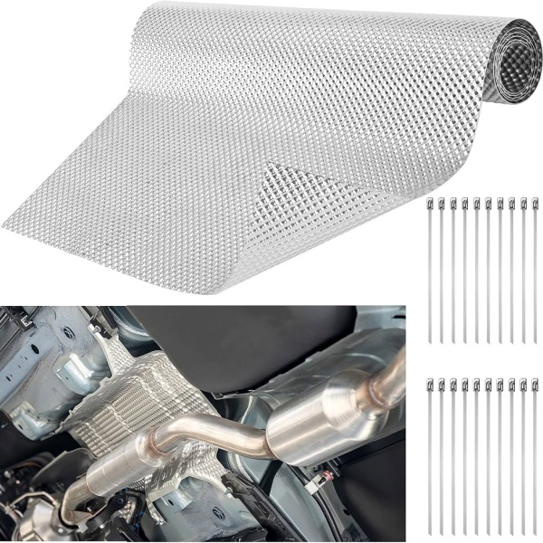
These two products are sometimes grouped under the same search terms, but their installation principles are different.
Rigid embossed aluminum sheet is normally mounted as a self-supporting or bracket-supported panel with a defined separation from the heat source.
Adhesive-backed thermal barrier is bonded to a suitable substrate and depends on the adhesive interface as part of the installation.
| Design Factor | Rigid Embossed Aluminum Sheet | Adhesive-Backed Barrier |
|---|---|---|
| Installation | Mechanical mounting or formed support | Bonded to an approved surface |
| Air gap | Can be deliberately designed into the assembly | Normally follows the substrate surface |
| Form | Self-supporting formed metal panel | Flexible or semi-flexible laminate |
| Main purchasing focus | Alloy, gauge, panel geometry and mounting | Layer construction, adhesive and substrate compatibility |
For bonded systems, see Peel and Stick Heat Shield: Where to Use It and How to Choose the Adhesive.
Do not replace a stand-off metal shield with an adhesive sheet and assume the thermal system remains equivalent. The installation geometry has changed.
A transmission tunnel can be exposed to heat from exhaust pipes, catalytic converters or other exhaust components routed close to the center of the vehicle.
The heat shield may need to follow a long, relatively narrow body contour while avoiding:
For a formed aluminum transmission tunnel heat shield, create the finished geometry before finalizing the flat blank.
Long side flanges can increase stiffness, but they also change the required material width and may reduce available clearance. The design should be checked in the complete assembly rather than as an isolated sheet-metal part.
A broad floor panel does not necessarily need to cover every square centimeter above the exhaust.
Identify the actual hot component and the portion of the body receiving unacceptable thermal exposure.
The barrier should interrupt the relevant radiant path while maintaining:
Extending a shield far beyond the affected area adds material and weight without automatically improving protection.
Underbody exhaust routing can also pass near a fuel tank, but fuel-tank shielding should not be treated as merely another section of floor pan.
Tank material, support straps, fuel lines, ventilation connections, electrical components and available clearance all affect the design.
A rigid aluminum panel can be considered as a separate supported barrier where the vehicle design permits it, but attachment should be made only to approved structural locations. Do not drill into or modify a fuel tank to install a heat shield.
Fuel-system thermal protection requires its own engineering and validation requirements rather than simply copying the floor-pan shield drawing.
One advantage of an underbody metal shield is that it can protect multiple nearby components from one exhaust heat source.
However, the shield should not make those components impossible to inspect or service.
When lines or harnesses run close to the panel, show them on the installation drawing and check:
Where one individual line requires additional localized thermal protection, use an appropriate sleeve or barrier rather than extending the underbody panel without evaluating the new geometry.
Mounting points determine whether the panel remains stable at vehicle speed and after repeated thermal cycling.
The design should specify:
Do not use mounting bolts to pull a badly formed panel into the correct position. Excessive assembly restraint can create local stress and distort the designed clearance.
The released panel should already conform sufficiently closely to the required installed geometry.
An underbody heat shield operates in continuous airflow and vehicle vibration. A large unsupported panel can move even when its thermal performance is acceptable.
Embossing can increase panel stiffness, while formed beads, flanges or carefully positioned mounting points can provide additional structural control.
During prototype testing, inspect for:
If a failure appears near one mounting location, identify the mechanical cause before simply increasing the entire sheet thickness.
BSTFLEX currently lists embossed aluminum thermal barrier sheets in:
Custom dimensions can also be discussed for OEM projects.
A large floor or tunnel heat shield should not automatically use the largest sheet. First develop the finished component and flat blank, then determine which purchased format provides the best material utilization.
For repeat production, evaluate:
For a detailed sizing workflow, see the BSTFLEX guide to aluminum heat shield sheet sizes for OEM fabrication.
Define the required supply stage before requesting quotations.
| Supply Stage | Buyer Receives | Main RFQ Information |
|---|---|---|
| Raw sheet | Rectangular embossed aluminum panel | Alloy, temper, gauge, pattern, length and width |
| Cut blank | Flat outline ready for later forming | Blank drawing, tolerances, pattern orientation and edges |
| Formed underbody shield | Three-dimensional panel ready for further assembly or installation | Finished drawing, bends, flanges, tabs, holes and datums |
| Complete thermal assembly | Metal panel plus any specified additional layers or hardware | Complete stack-up, attachments and validated performance requirements |
For fully formed metal parts, customers can also review the BSTFLEX Metal Stamping Heat Shields range.
A successful material inspection does not prove that the installed shield protects the vehicle floor.
The final assembly should be checked under the relevant vehicle operating conditions.
Measure the protected body or component at defined locations. Record the operating condition, duration, airflow and heat-source condition.
Check the minimum distance from the exhaust across thermal expansion, vibration and expected vehicle movement.
Inspect mounting holes, tabs, flanges and broad panel areas after the required vehicle or laboratory durability cycle.
Evaluate exposure relevant to the installation, which can include water, road contamination, debris and corrosion.
Confirm that the shield does not prevent access to exhaust fasteners, sensors, underbody lines or other parts that require maintenance.
| RFQ Item | Information to Provide |
|---|---|
| Application | Floor pan, exhaust tunnel, transmission tunnel, muffler zone or other underbody area |
| Heat source | Exhaust pipe, catalytic converter, muffler or other component |
| Protected component | Vehicle floor, line, harness or another temperature-sensitive part |
| Aluminum specification | Alloy, temper and applicable customer material requirement |
| Base-metal thickness | Nominal gauge and tolerance where controlled |
| Embossing | Pattern, orientation and any areas required to remain flat |
| Finished geometry | Overall shape, bends, flanges, mounting tabs and edge details |
| Clearances | Minimum distances from exhaust and adjacent moving components |
| Supply form | Raw sheet, blank or formed component |
| Validation | Thermal, vibration, environmental and service requirements |
| Quantity | Prototype quantity, batch quantity and annual forecast |
Aluminum is widely suitable for lightweight underbody radiant barriers because it is formable and has low density. Stainless steel can be considered where the location has higher thermal or mechanical demands. Final material selection should follow the actual installation.
Yes. Embossed aluminum sheet can be cut and formed into transmission or exhaust tunnel barriers. The design should maintain required exhaust clearance, vehicle service access and mounting stability.
A rigid stand-off heat shield is normally designed with controlled separation from the hot exhaust component. Direct contact changes the heat-transfer path and should not be introduced unless it is part of an engineered and validated construction.
No. Increased thickness can improve mechanical stiffness but also adds weight. Thermal protection also depends on coverage, air gap, surface, formed geometry and mounting. The complete assembly should be evaluated.
Not automatically. A mechanically supported metal panel and an adhesive-backed laminate use different installation principles. Replacing one with the other changes the air gap and thermal construction and requires validation.
Embossing creates three-dimensional geometry that can increase the rigidity of thin aluminum, helping broad panels maintain their shape without relying solely on increased sheet thickness.
BSTFLEX supplies embossed aluminum thermal barrier sheet and supports custom sizes and drawing-based heat shield projects. Send the material specification and finished geometry so the required supply scope can be reviewed.
BSTFLEX supplies Embossed Aluminum Thermal Barrier Sheet for floor pans, exhaust tunnels, transmission tunnels, bulkheads and other automotive heat-protection applications.
Send the underbody assembly drawing together with the aluminum specification, base-metal thickness, embossing requirement, finished panel dimensions and prototype quantity. Show the exhaust position, mounting points and required clearances so the material and geometry can be reviewed together.
If the installation requires greater mechanical or high-temperature capability than the selected aluminum construction can provide, BSTFLEX also supplies embossed stainless steel heat shield material and Alloy 625 Inconel heat shield material for separate engineering evaluation.
Send your underbody heat shield drawing and RFQ to BSTFLEX for sheet, blank, prototype and OEM production review.

No.10, Chuangxin North Road, Nanshan Park, Ningguo Economic and Technological Development Zone, Ningguo City, Anhui Province, China
هاتف/Whatsapp : 0086-15856303740
البريد الإلكتروني : sales@bstbraidedsleeve.com
Skype : vanesa-cheng