عن ماذا تبحث?
Quick answer: measure the turbine housing, not the compressor cover. Record the housing circumference and cover width, then document the inlet, outlet, wastegate arrangement, actuator movement, fastening access and surrounding clearances. A turbo model or T3/T4/T6 name is useful, but it is not enough to approve a custom blanket pattern.
A reliable custom turbo blanket project begins with a measurement package that another person can understand without guessing where each dimension was taken. The most useful package combines labeled dimensions, installed photographs, turbocharger identification and a clear description of the area that must be insulated.
This guide explains how to collect those details for a turbine-housing thermal blanket. It does not apply to a compressor-side containment blanket. For available materials and standard pattern families, review the BSTFLEX turbo heat shield blanket range.
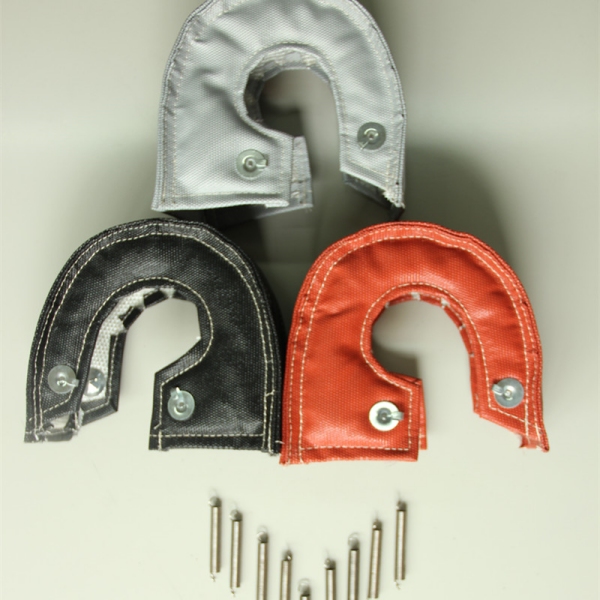
Measure the exhaust-driven turbine housing, commonly called the hot side. This is the housing connected to the exhaust manifold and the downstream exhaust connection. Do not use the outside diameter of the compressor cover as the blanket size.
Before recording dimensions, identify the following components on a photograph:
The blanket should cover the intended turbine-housing area while preserving the clearance, movement and access required by the installation.
For an initial fitment review, provide the turbocharger identification together with at least the following measurements and photographs.
| Item | What to Record | Why It Is Needed |
|---|---|---|
| Turbo identification | Manufacturer, model, part number and turbine-housing reference where available. | Helps compare the inquiry with existing patterns and known housing variants. |
| Housing circumference | Circumference around the main turbine-housing body, excluding flanges and unrelated brackets. | Establishes how far the blanket must wrap around the housing. |
| Cover width | Width of the housing area to be covered, measured between the intended blanket boundaries. | Helps define the blanket depth and edge positions. |
| Inlet and outlet geometry | Flange or V-band type, orientation, outside profile and service-access requirements. | Prevents the pattern and fastening from obstructing connections or clamps. |
| Wastegate arrangement | Internal or external wastegate; actuator body, bracket, rod and lever positions where relevant. | Determines whether a clearance cutout or revised edge is required. |
| Available clearance | Smallest gaps to lines, wiring, bodywork, brackets, shields and moving parts. | Confirms whether the proposed insulation thickness and fastening can fit safely. |
| Installed photographs | Overall, inlet side, outlet side, actuator side and top view, with a ruler or scale where useful. | Shows geometry and surrounding restrictions that individual dimensions may not capture. |
| Coverage boundary | Mark the area to be insulated and components that must remain uncovered or accessible. | Defines the actual design objective instead of leaving the blanket boundary to assumption. |
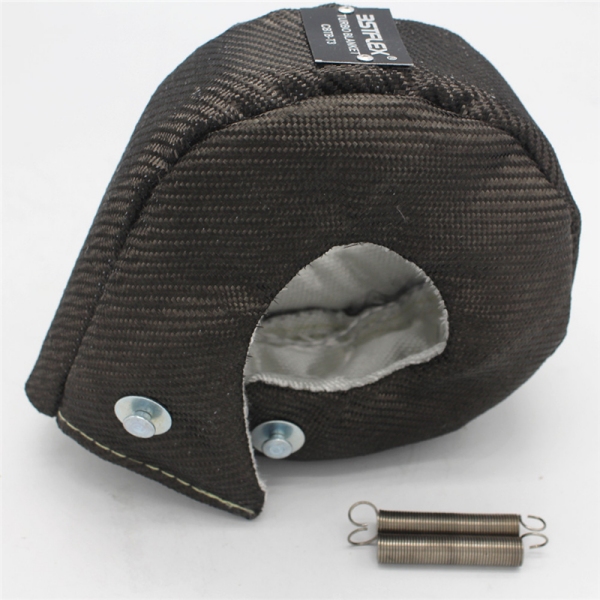
Use tools that match the geometry and access available:
Do not measure until the turbocharger and adjacent exhaust components are completely cool. Follow the equipment service procedure and prevent unexpected engine starting before working in the installation area.
Record the turbocharger manufacturer, full model and part number. When possible, also photograph the identification plate, casting marks or housing reference.
This information matters because one turbo family may be supplied with different turbine housings, wastegate arrangements, outlet connections or area-ratio options. The compressor model alone may not identify the hot-side housing used in the installation.
For vehicle or equipment applications, also state:
Take photographs before removing surrounding parts. The installed view shows restrictions that may disappear when the turbocharger is placed on a workbench.
Recommended views include:
Use arrows or labels to identify the hot side, moving components, service fasteners and the proposed blanket boundary. When scale is important, place a ruler in the same plane as the feature being photographed.
Wrap a flexible tape around the main body of the turbine housing. Keep the tape on the housing area the blanket will surround. Do not include the compressor cover, inlet flange, outlet flange, V-band clamp, actuator bracket or unrelated pipework unless the approved design specifically requires coverage there.
If access prevents a direct reading:
Write the unit beside every dimension. Do not submit an unlabeled number that could be interpreted as millimeters, inches, diameter or circumference.
Circumference is the distance around the housing. Diameter is a straight-line dimension across a circular section. They are not interchangeable. If both are supplied, label them separately and show where each was taken.
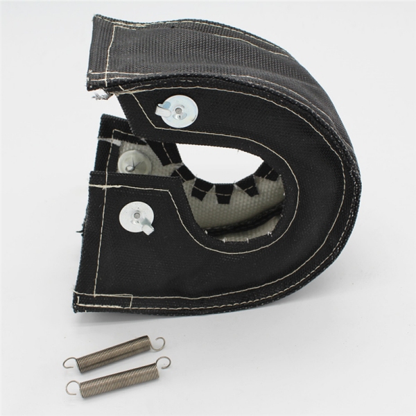
Measure the side-to-side width of the turbine-housing area that the blanket needs to cover. The dimension should stop at the intended blanket edges rather than including the complete turbocharger width.
Exclude the compressor cover and center housing unless part of an approved design requires an overlapping edge. Also identify any flange, clamp, boss or bracket that changes the available width.
For an irregular housing, provide more than one width:
Show whether the turbine inlet and outlet use bolted flanges, V-band connections or another arrangement. Record the orientation and indicate which clamps or fasteners must remain accessible after the blanket is installed.
For a V-band outlet, include the clamp position and the space needed to reach its fastener. For a divided or twin-scroll housing, show the inlet geometry and any center divider or manifold arrangement that affects the blanket boundary.
The blanket should not be approved from housing circumference and width alone when the inlet or outlet geometry changes the available fastening route.
An internally wastegated housing needs additional information because the actuator rod and turbine-side lever must move without contacting the blanket, anchors, springs or lacing wire.
Provide:
Mark these details on photographs or a drawing. Do not assume that every T25/T28, T3 or T4 internal-wastegate housing uses the same cutout.
A custom pattern should provide the required clearance by design. Cutting a finished standard blanket after delivery should not be treated as the default solution to uncertain fitment.
With an external wastegate, the actuator may not be mounted on the turbine housing, but surrounding pipework can still restrict the blanket edge and hardware route.
Show the wastegate branch, nearby manifold tubes, clamps, sensor bungs and any support brackets. Identify whether the blanket must stop before a wastegate take-off or whether a separate insulation component will be used on the adjacent pipework.
The turbo blanket covers the turbine housing. It should not be assumed to insulate every manifold branch, wastegate pipe or downpipe in the surrounding exhaust system.
Measure the smallest gaps between the turbine housing and surrounding components. Include the expected blanket thickness when reviewing whether the design will fit.
Important clearance locations may include:
If an original metal shield will remain, provide its position and mounting details. The article Turbo Blanket vs Heat Shield explains why a flexible blanket and rigid shield require different fitment checks.
A custom turbo blanket drawing should show both what must be covered and what must remain open.
Mark:
This is more useful than asking for “maximum coverage” without defining service and movement requirements.
Fitment cannot be separated completely from material construction. A thicker insulation package may occupy more space, change the edge position or require a revised fastening arrangement.
BSTFLEX outer-cover options include:
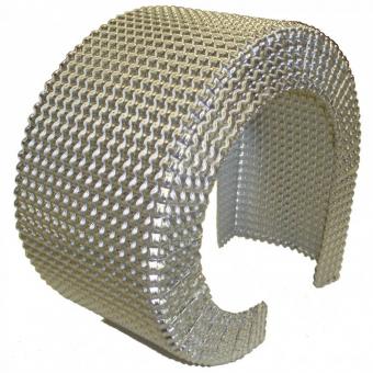
An optional embossed metal foil layer can also be reviewed according to the required metal grade, thickness, embossing pattern, position and coverage. This option is separate from an aluminized fabric outer cover.
For silicone-coated construction, see Silicone Coated Turbo Blankets: Outer-Cover Temperature vs Turbine-Side Insulation. The outer material should be specified together with the internal insulation, edge construction, thread and fastening.
A professional CAD drawing is useful but not always required for the first review. A clear marked sketch can be sufficient when it contains traceable dimensions and matching photographs.
Every measurement drawing should include:
Do not place several unlabeled arrows on one photograph. Use references such as A, B, C and D, then define each dimension in a separate table.
| Suggested Reference | Measurement | How to Define It |
|---|---|---|
| A | Turbine-housing circumference | Distance around the selected main housing path, excluding flanges unless noted. |
| B | Required cover width | Distance between the proposed blanket edge boundaries. |
| C | Wastegate location | Distance from an identified housing reference point to the actuator linkage or required cutout center. |
| D | Minimum installation clearance | Smallest available gap at the named component before insulation is installed. |
| E | Inlet or outlet access | Clearance required around the flange, clamp or service fastener. |
| Photograph | What It Should Show |
|---|---|
| Overall installation | Turbocharger position and surrounding engine, vehicle or equipment components. |
| Turbine-housing close-up | Main housing profile and the path used for circumference measurement. |
| Side view | Housing width, center housing, outlet and proposed blanket edge. |
| Wastegate view | Actuator, bracket, rod, lever and required movement clearance. |
| Connection view | Inlet, outlet, clamp, flange and service-fastener access. |
| Limited-clearance area | Smallest gap to a line, wire, bracket, shield or body panel, with a scale where possible. |
A turbine-side thermal blanket is selected around the hot-side housing. Compressor-cover measurements do not establish the required blanket pattern.
T3, T4 and T6 names help organize product families, but housings within a family can differ. Confirm the actual housing dimensions and installation.
State exactly what the tape passed over. A supplier cannot compare dimensions reliably when one circumference includes a flange and another does not.
Label the dimension type and unit. A number without its measurement path can result in an incorrect pattern.
A static photograph of the linkage does not define its required operating envelope. Show the mechanism and identify the clearance that must be maintained.
Bench measurements may describe the housing but not the installed clearance, hardware access or nearby components. Include installed photographs whenever possible.
A pattern approved for one insulation construction may need review when the thickness or layer arrangement changes.
A standard T25/T28, T3, T3/T4, T4 or T6 pattern may be suitable when the actual housing and surrounding installation match the pattern requirements. A custom pattern should be considered when:
The BSTFLEX OEM and custom turbo blanket guide explains the broader material, sampling, branding and production requirements.
Measurements are the design input. The installed sample is the fitment confirmation.
During sample approval, check:
Record the accepted pattern revision and photograph the installed sample. Any modification made during trial fitting should be transferred to the controlled drawing before repeat production.
| RFQ Section | Information to Provide |
|---|---|
| Turbocharger | Manufacturer, model, part number, housing reference and whether original or aftermarket. |
| Equipment | Vehicle, engine, marine engine, generator, industrial machine or other application. |
| Dimensions | Housing circumference, cover width, wastegate location and minimum clearances, with units. |
| Installation | Photographs, inlet/outlet arrangement, actuator details, clamps, lines and service requirements. |
| Coverage | Marked area to insulate and components that must remain accessible or uncovered. |
| Thermal conditions | Known continuous and peak conditions, measurement locations and protected-component target where available. |
| Construction | Outer cover, internal insulation requirements, reinforcement, edge, thread and fastening preference. |
| Embossed metal foil | Whether required; metal grade, thickness, embossing, position and coverage if defined. |
| Commercial requirements | Sample quantity, initial order, repeat demand, logo, label, packaging and required documents. |
The most common starting dimensions are turbine-housing circumference and the width of the area to be covered. A complete fitment review may also require wastegate location, inlet and outlet geometry, and installation-clearance dimensions.
For a new fitment, measure the actual turbine housing and installation. An existing blanket can be supplied as a reference sample, but its dimensions alone do not prove that its fit, materials or coverage are correct for the new project.
Use the flange or family name only as a starting reference. Confirm the turbine-housing dimensions, wastegate arrangement and available space before approving the pattern.
Document the actuator, bracket, rod and turbine-side lever relative to a defined housing reference point, and identify the complete area required for movement and blanket clearance.
Photographs are useful for reviewing geometry and restrictions, but labeled dimensions, a drawing, a physical sample or the turbocharger itself may be required depending on the complexity and accuracy needed.
They may use the same basic housing geometry, but a change in insulation thickness, reinforcement or layer arrangement can affect fitment. Each proposed construction should be reviewed against the available clearance.
Send BSTFLEX the turbocharger identification, labeled dimensions, installed photographs and the area that needs thermal protection. Include the wastegate arrangement, available clearance, preferred outer material and expected order quantity.
For OEM and private-label projects, also provide the required logo, label, packaging, sample-approval criteria and production documentation. Clear measurement references allow the proposed pattern, materials and fastening to be reviewed before sampling.
Send Your Turbocharger Measurements and Drawing to BSTFLEX

No.10, Chuangxin North Road, Nanshan Park, Ningguo Economic and Technological Development Zone, Ningguo City, Anhui Province, China
هاتف/Whatsapp : 0086-15856303740
البريد الإلكتروني : sales@bstbraidedsleeve.com
Skype : vanesa-cheng